Removal Procedure
- Raise and support the vehicle. Refer to Lifting and Jacking the Vehicle
in General Information.
- Remove the front tire and wheel assembly. Refer to Tire and Wheel Removal and Installation
in Tires and Wheels.
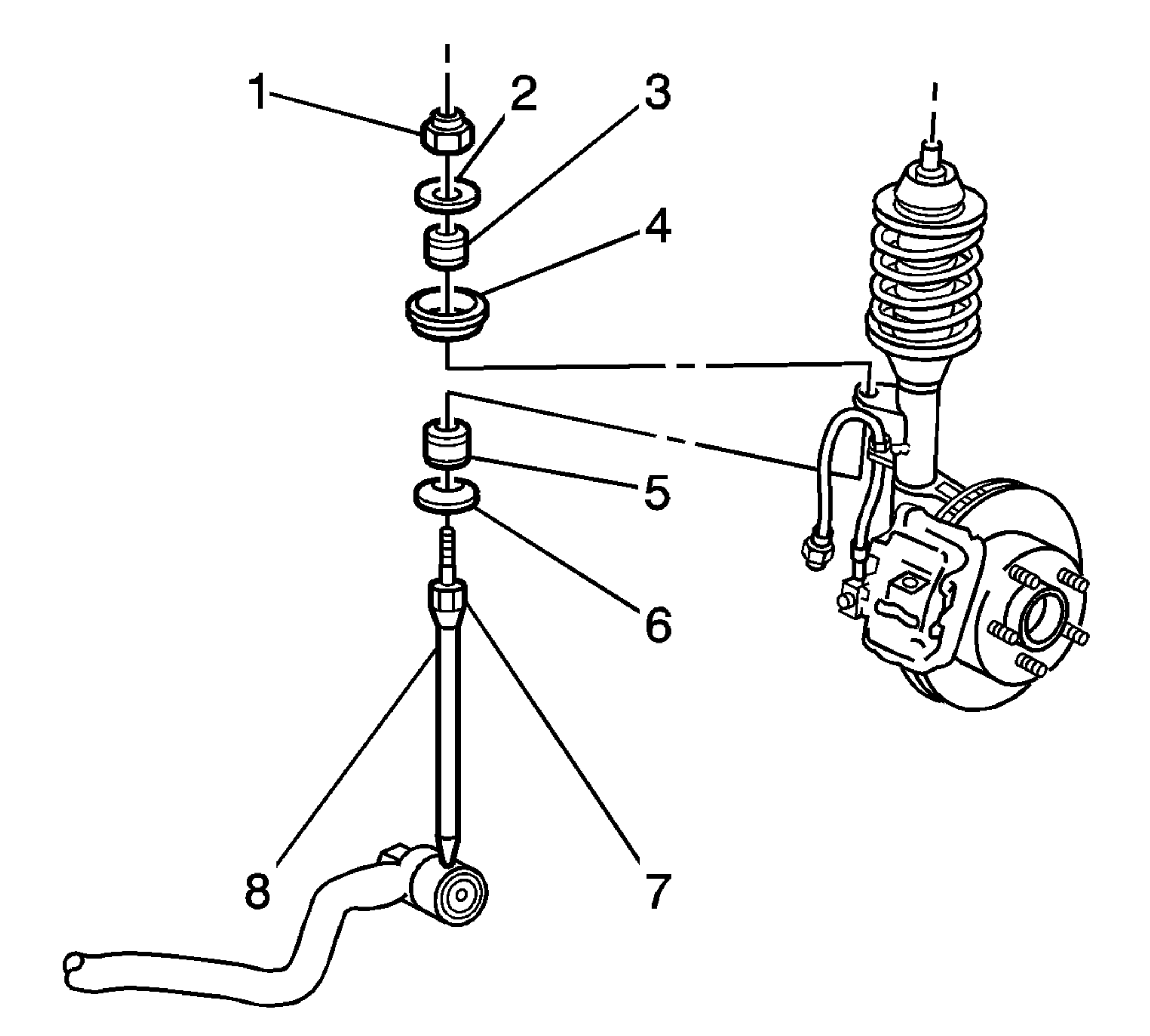 Courtesy of GENERAL MOTORS CORP.
- Use a wrench in order to hold the stabilizer shaft link upper stud (7).
- Remove the upper nut (1).
- Remove the upper washer (2).
- Remove the upper insulator (3).
- Remove the retainer (4).
- Separate the wheel speed sensor harness and the insulator from the strut bracket.
- Turn the sleeve that retains the brake hose to the strut bracket.
- Align the flats on the sleeve with the strut bracket opening.
- Separate the brake hose from the strut bracket.
- Position a jack and a block of wood below the control arm ball joint.
- Raise the jack in order to support the control arm.
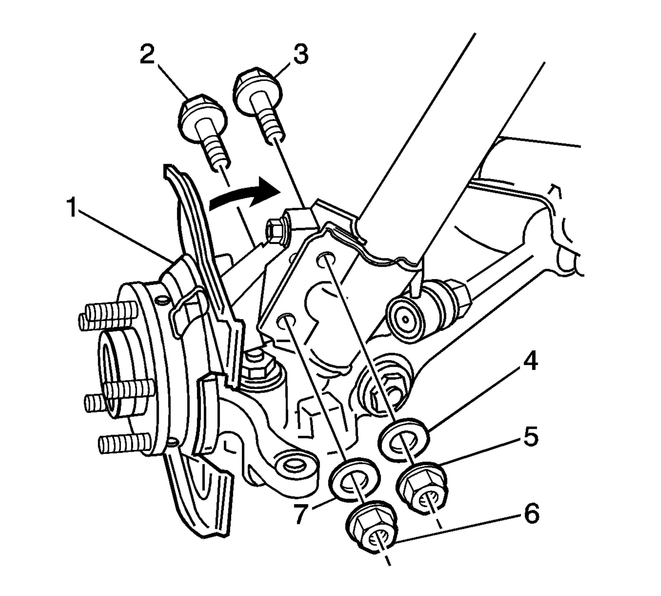 Courtesy of GENERAL MOTORS CORP.
- Remove and discard the 2 nuts (5,6).
- If equipped, remove the 2 washers (4,7).
- Remove and discard and the 2 bolts (2,3).
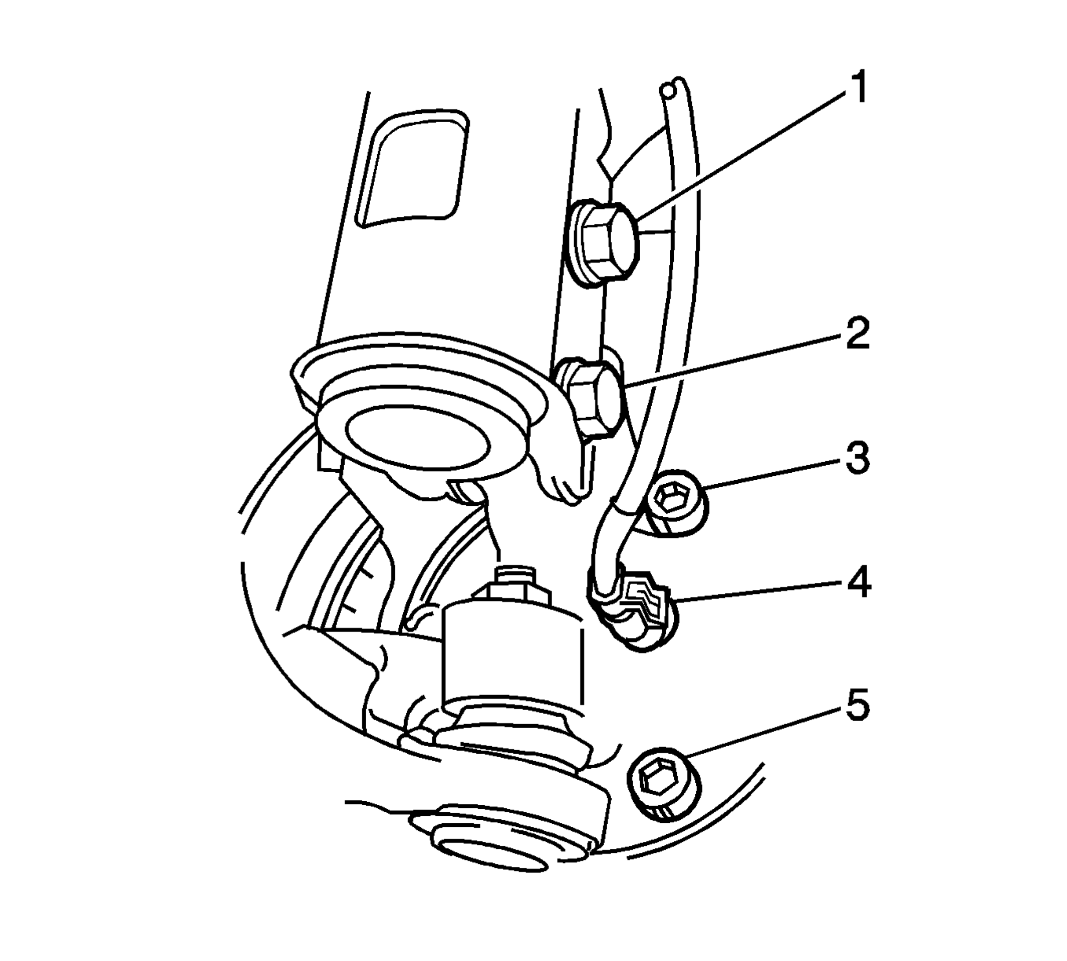 Courtesy of GENERAL MOTORS CORP.
- Lift the locking tab on the wheel speed sensor connector (4).
- Disconnect the wheel speed sensor connector from the knuckle.
- Separate the knuckle from the strut.
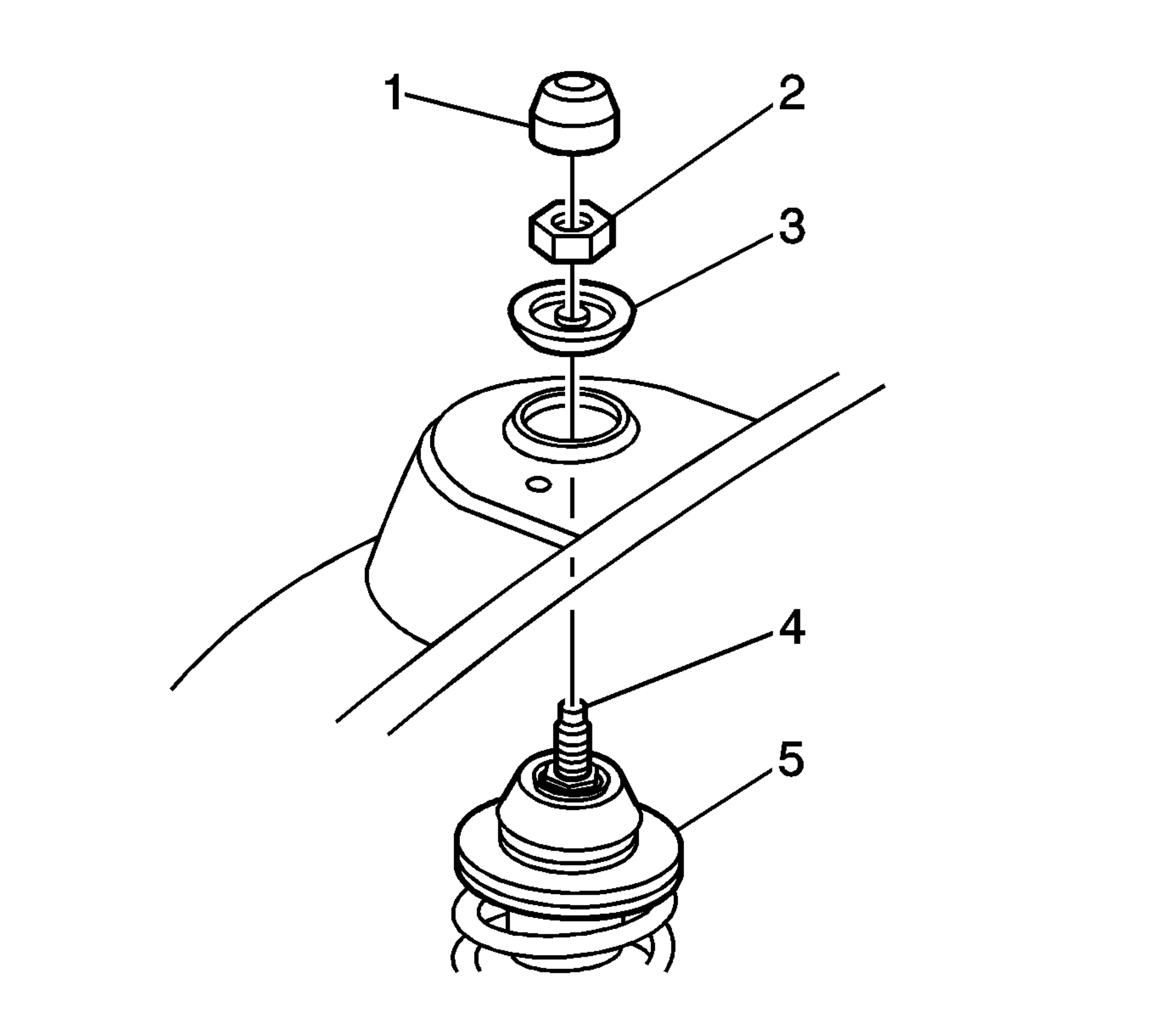 Courtesy of GENERAL MOTORS CORP.
- Remove the strut nut cap (1).
- Use a wrench in order to hold the end of the strut rod shaft (4).
- Remove and discard the strut nut (2).
- Remove the strut bumper stop (3).
- Lower the strut assembly.
- Remove the stabilizer shaft link from the strut bracket.
- Remove the strut assembly from the vehicle.