Removal Procedure
- Drain engine coolant.
- Remove engine cover.
 Courtesy of GENERAL MOTORS CORP.
- Remove air cleaner cap sub-assembly with hose.
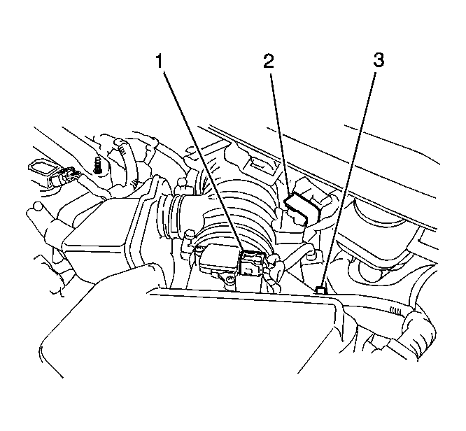
- Disconnect the mass air flow meter connector.
- Separate the 2 wire harness clamps.
 Courtesy of GENERAL MOTORS CORP.
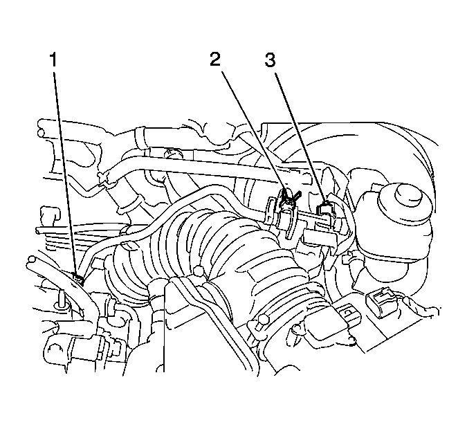
- Disconnect the NO. 1 vacuum switching valve connector and the 2 vacuum hoses.
 Courtesy of GENERAL MOTORS CORP.
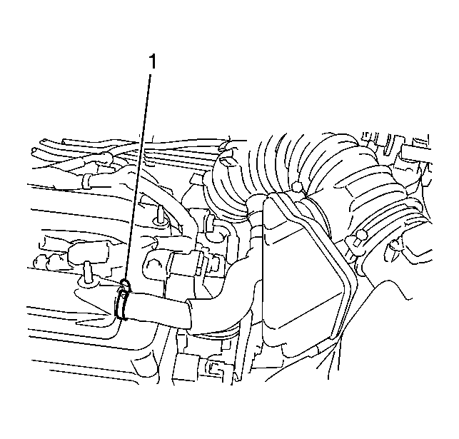
- Disconnect the ventilation hose.
 Courtesy of GENERAL MOTORS CORP.
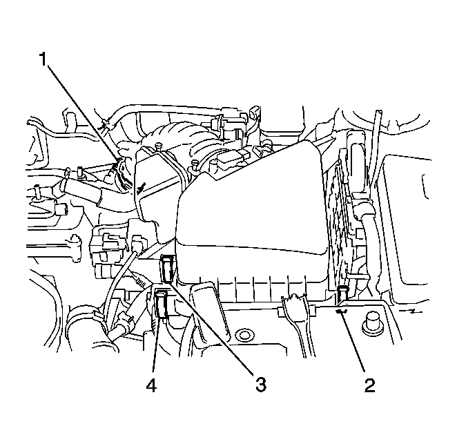
- Loosen the NO. 1 air cleaner hose clamp, and unlock the 3 air cleaner assembly clamps and remove the air cleaner cap sub-assembly with NO. 1 hose.
 Courtesy of GENERAL MOTORS CORP.
- Remove throttle body assembly.
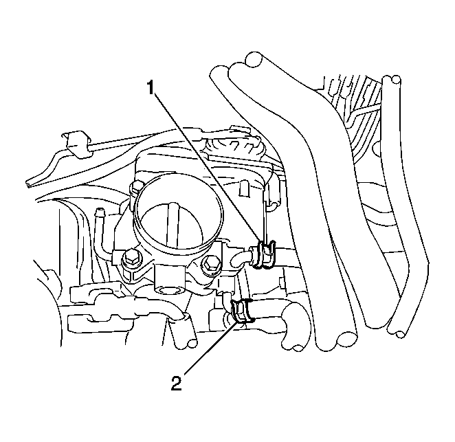
- Disconnect the 2 water by-pass hoses.
 Courtesy of GENERAL MOTORS CORP.
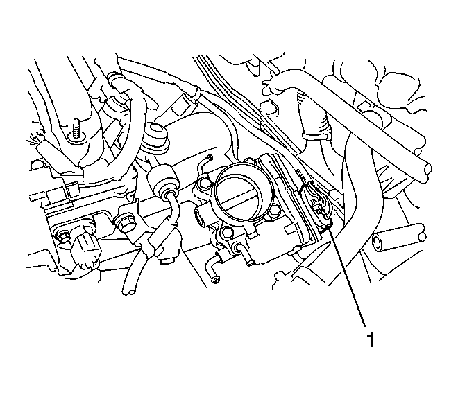
- Disconnect the throttle body assembly connector.
 Courtesy of GENERAL MOTORS CORP.
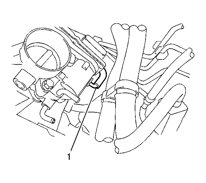
- Disconnect the throttle body hose.
 Courtesy of GENERAL MOTORS CORP.
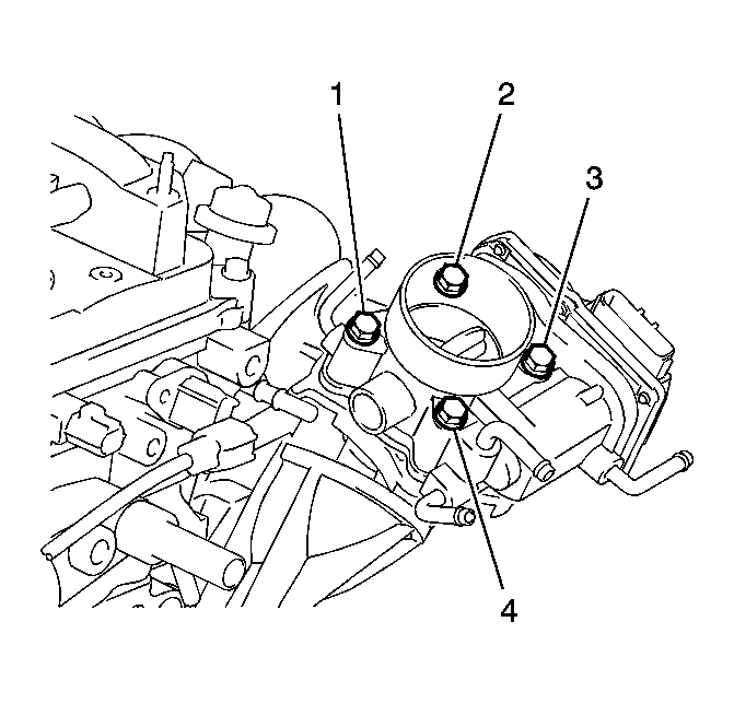
- Remove the 4 bolts and throttle body assembly.
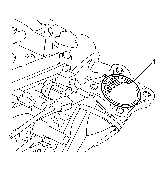 Courtesy of GENERAL MOTORS CORP.
- Remove the gasket from the intake manifold.