Diagnostic Procedure
- Install scan tool. Perform On-Board Diagnostic (OBD) system check. See
ON-BOARD DIAGNOSTIC (OBD) SYSTEM CHECK in appropriate SELF-DIAGNOSTICS article. Check for stuck Throttle Position (TP) sensor. Ensure Engine Coolant Temperature (ECT) sensor value reads close to ambient temperature. Check for fuel injector Diagnostic Trouble Codes (DTCs). If fuel injector DTCs are present, diagnose DTCs first. See
appropriate SELF-DIAGNOSTICS article. If fuel injector DTCs are not present, go to next step.
- If DTC P1635 is present, diagnose DTC first. See
appropriate SELF-DIAGNOSTICS article. If DTC P1635 is not present, go to next step.
- If any Ignition Control (IC) related DTC is present, diagnose DTC first. See
appropriate SELF-DIAGNOSTICS article. If DTC is not present, go to next step.
- If an EGR related DTC is present, diagnose DTC first. See
appropriate SELF-DIAGNOSTICS article. If EGR DTC is not present, go to next step.
- Using scan tool, monitor engine RPM (7X CKP reference pulse) while cranking engine. If RPM is detected, go to next step. If RPM is not detected, go to step 15
.
- If scan tool 7X counter reads more than 100 counts, go to next step. If scan tool 7X counter reads 100 counts or less, go to step 10
.
- Check for spark at cylinders No. 2 and 4. If spark is present, check for fouled spark plugs. If spark plugs are okay, go to step 11
. If spark is not present, go to next step.
- Check EIS fuse (10-amp), located in underhood fuse block, or voltage to fuse with ignition on. See Fig 1
. If fuse is okay and voltage is present, go to next step. If fuse is faulty or voltage is not present, replace fuse or repair circuit.
- Disconnect Electronic Ignition (EI) module harness connector. Turn ignition on. Using a test light, check for voltage between ground and terminal "A" at EI module harness connector. See Fig 1
. If voltage is present, check EI module connector tightness. If connector is okay, EI module is faulty. If voltage is not present, repair open in Pink wire (circuit No. 1039) between EI module and instrument panel fuse block.
- Check for spark at plug wires of cylinders No. 2 and 4. If spark is present at both wires, go to next step. If spark is not present at either plug wire, check for 12 volts and ground to EI module. See Fig 1
. Repair as necessary. If spark is present at only one plug wire, check spark at opposing cylinder. If spark is present at opposing cylinder, replace spark plug wire. If spark is not present at opposing cylinder, replace EI module.
- Reconnect EI module harness connector. Install Fuel Pressure Gauge (SA9127E). Turn ignition on. Fuel pressure reading should be 38-44 psi (2.7-3.1 kg/cm2
). If fuel pressure is as specified, see appropriate
TROUBLE SHOOTING - NO CODES article. If fuel pressure is not as specified, go to next step.
- Turn ignition off. Using a test light connected to ground, probe FUEL PUMP fuse (10-amp), located in instrument panel fuse block. See Fig 2
. Turn ignition on. Test light should illuminate for 2 seconds, and then turn off. If test light illuminates and turns off after about 2 seconds, check for open in fuel pump circuit (Gray wire) or ground circuit (Black wire). If circuits are okay, check fuel pump. If test light does not illuminate, go to next step.
- Turn ignition off. Repeat test with test light inserted in instrument panel fuse block probe hole. See Fig 2
. If test light does not illuminate, check for open or short to ground in Dark Green/White wire between fuel pump relay and PCM. If circuit is okay, check PCM connector tightness or for faulty PCM. If test light illuminates, go to next step.
- Remove fuel pump relay. Using a test light connected to ground, probe Red wire terminal of fuel pump relay connector (relay socket) in instrument panel fuse block. See Fig 2
. If test light illuminates, check fuel pump relay connector tightness. Check for faulty fuel pump relay ground or for faulty fuel pump relay. If test light does not illuminate, check for faulty I/P BATT fuse (30-amp), located in underhood fuse block. If fuse is okay, repair open in Red wire between fuel pump relay and underhood fuse block.
- Turn ignition off. Disconnect PCM connector J3. See Fig 1
. Using DVOM, measure resistance between PCM connector J3, terminals D13 (7X ref hi circuit) and D14 (7X ref lo circuit). Resistance should be 700-900 ohms. If resistance is as specified, go to next step. If resistance is not as specified, go to step 17
.
- Set DVOM to AC scale. Connect DVOM between PCM connector J3, terminals D13 (7X ref hi circuit) and D14 (7X ref lo circuit). See Fig 1
. Crank engine. DVOM should display 200 millivolts. If voltage is as specified, check PCM connector tightness. If voltage is not as specified, replace Crankshaft Position (CKP) sensor.
- Check for continuity in 7X ref hi circuit (Yellow wire) and 7X ref lo circuit (Purple wire). See Fig 1
. Repair as necessary. If continuity is present, check circuits for short to ground or voltage. Repair as necessary. If circuits are okay, go to next step.
- Remove Crankshaft Position (CKP) sensor. Measure CKP sensor resistance. Resistance should be 700-900 ohms. If resistance is not as specified, replace CKP sensor. If resistance is as specified, go to next step.
- Check if CKP sensor is still magnetized. If sensor is not magnetized, replace CKP sensor. If sensor is magnetized, check for poor or intermittent connection at sensor connector. Repair as necessary.
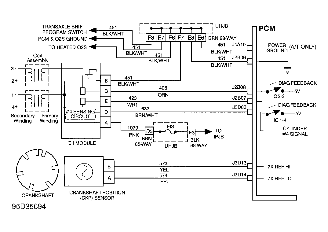 Courtesy of GENERAL MOTORS CORP.
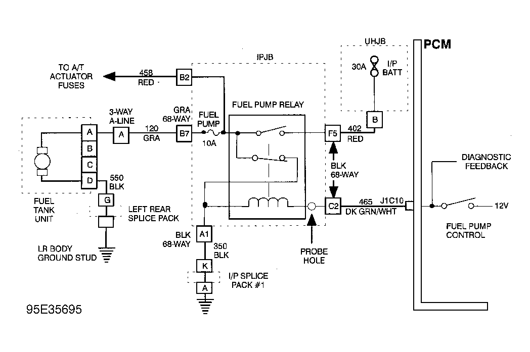 Courtesy of GENERAL MOTORS CORP.