Removal Procedure
 Courtesy of GENERAL MOTORS CORP.
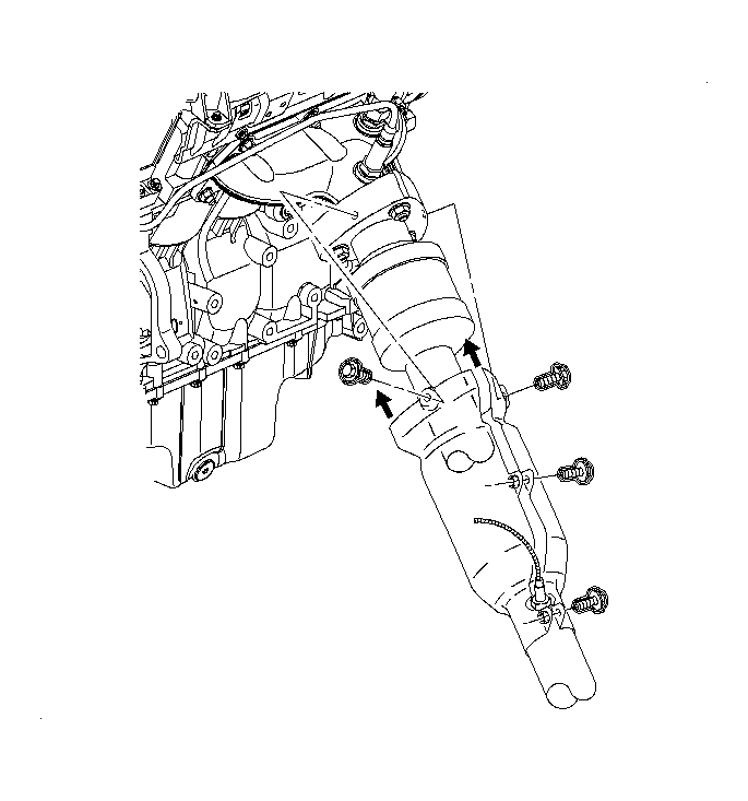
- If equipped with a L81 engine, remove the rear exhaust manifold pipe heat shield. Refer to Exhaust Pipe Heat Shield Replacement
in Engine Exhaust.
 Courtesy of GENERAL MOTORS CORP.
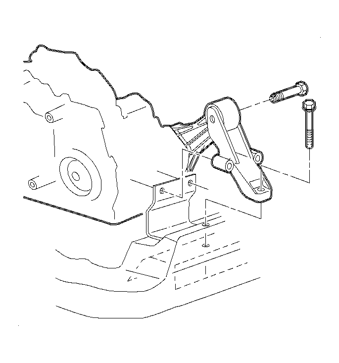
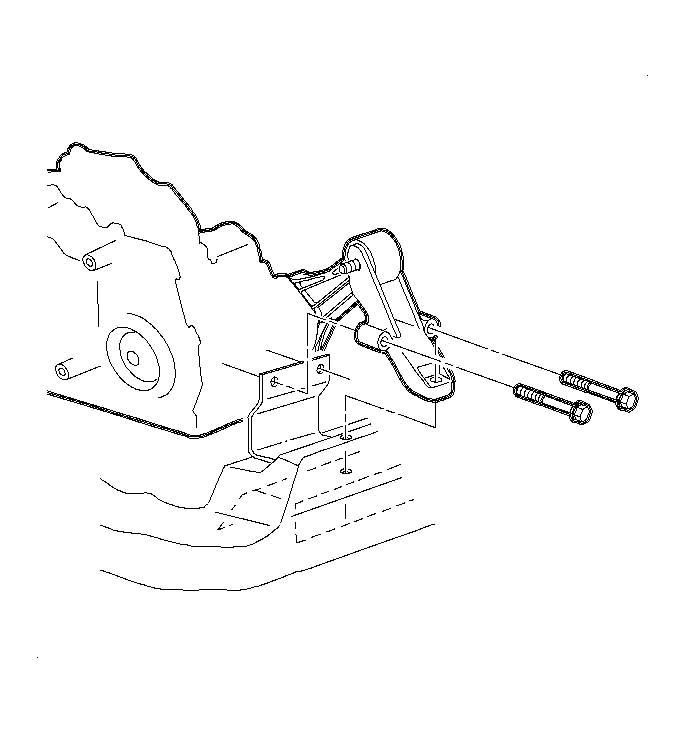
- Remove the rear transaxle mount through bolt and transaxle mount to frame bolt.
 Courtesy of GENERAL MOTORS CORP.
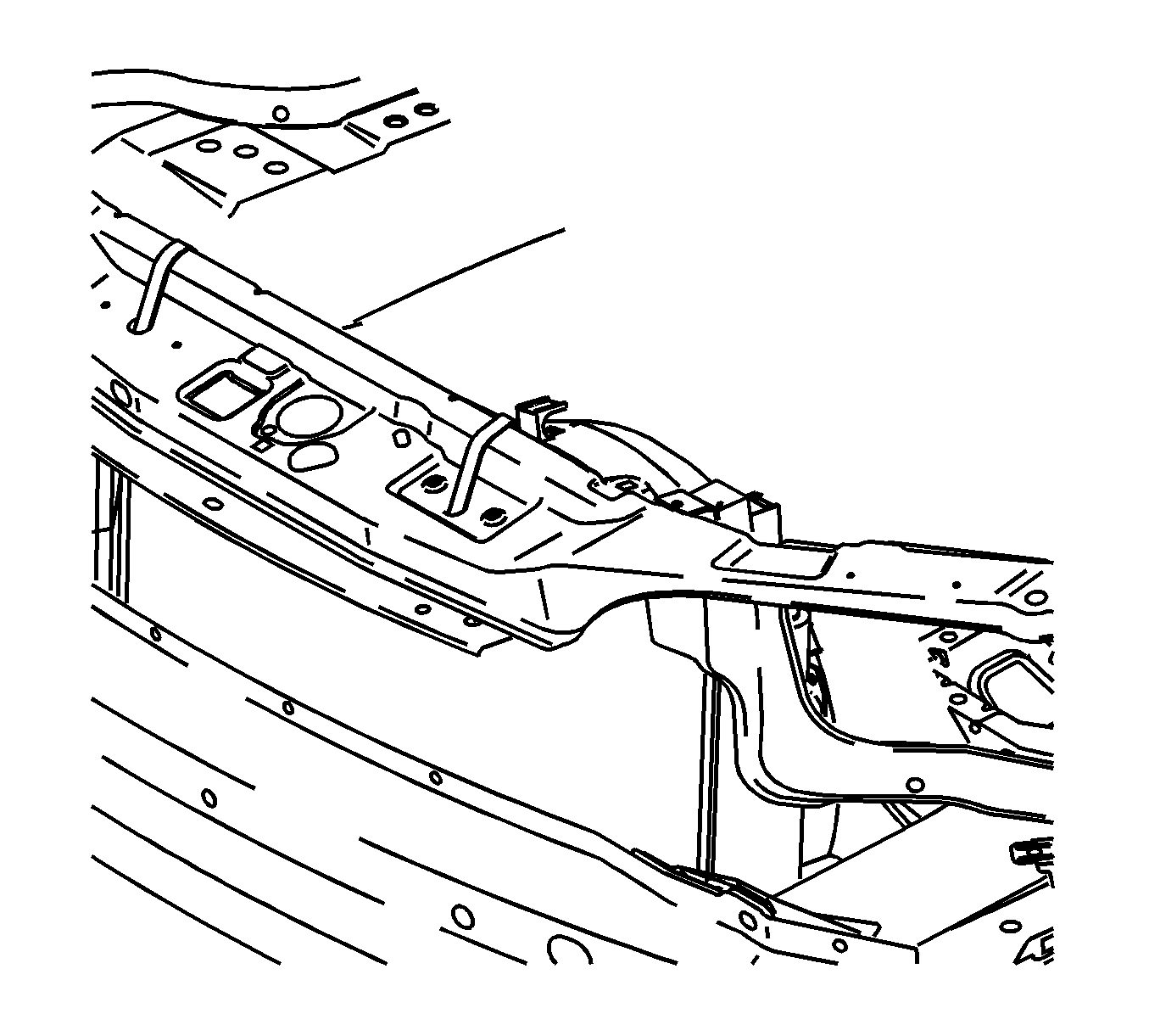
- Secure the radiator to the upper radiator support.
- Raise and support the vehicle. Refer to Lifting and Jacking the Vehicle
in General Information.
- Remove the front tires and wheels. Refer to Tire and Wheel Removal and Installation
in Tires and Wheels.
 Courtesy of GENERAL MOTORS CORP.
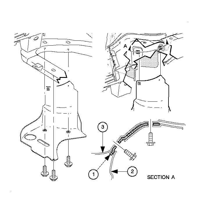
- Remove the right front lower splash shield (2).
- Remove the left front wheel liner push pin from the frame.
 Courtesy of GENERAL MOTORS CORP.
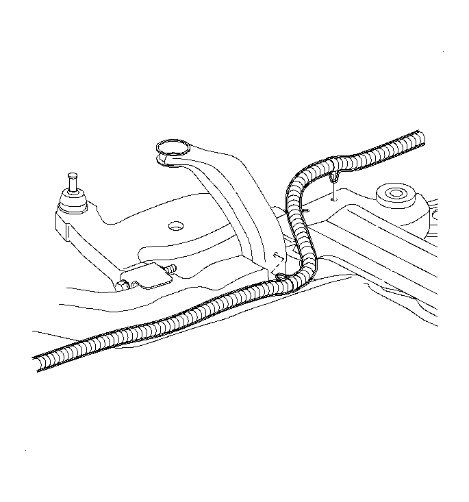
- Disconnect the rear oxygen (O2) sensor harness push pins from the frame.
 Courtesy of GENERAL MOTORS CORP.
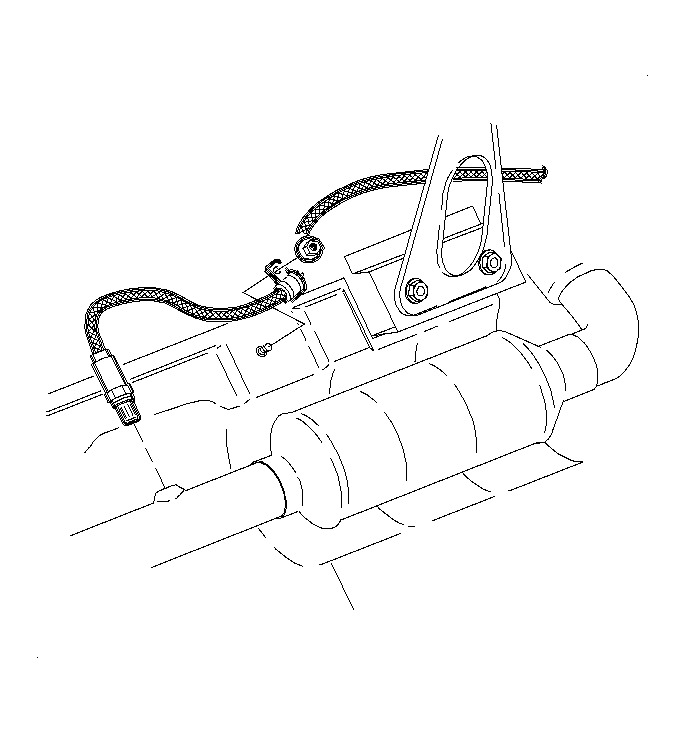
- If equipped with a L61 engine, remove the O2 sensor harness to underbody clamp attachment nut.
- Disconnect the exhaust manifold pipe from the exhaust manifold on L61 engine or manifolds on the L81 engine. Refer to Exhaust Manifold Pipe Replacement (Automatic Transmission - L61)
or Exhaust Manifold Pipe Replacement (Manual Transmission - L61)
in Engine Exhaust.
 Courtesy of GENERAL MOTORS CORP.
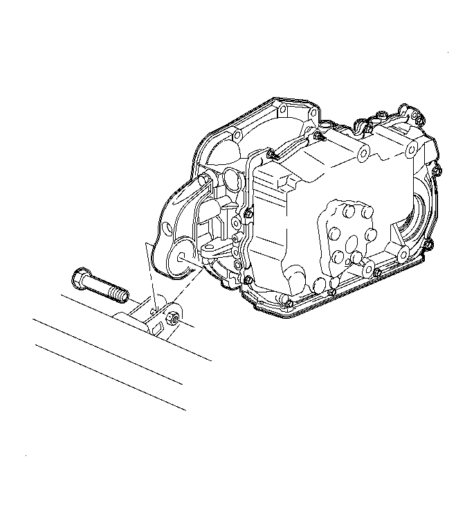
- Remove the front transaxle mount through bolt.
 Courtesy of GENERAL MOTORS CORP.
- Remove the remaining rear transaxle mount to frame bolts.
- Remove the rear transaxle mount from the vehicle.
 Courtesy of GENERAL MOTORS CORP.
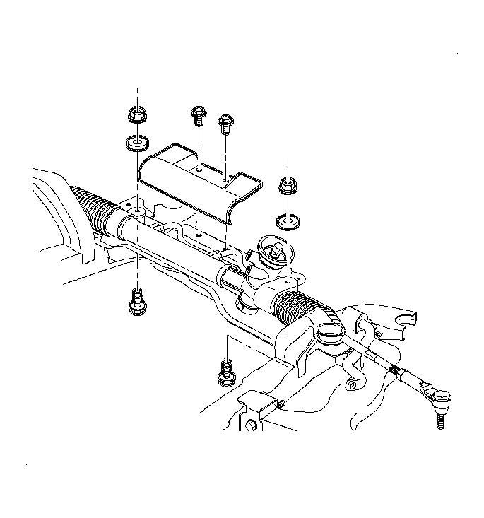
- Remove the steering gear to frame bolts and nuts. Discard the bolts and nuts.
- If equipped with a L61 engine, remove the steering gear heat shield. Refer to Power Steering Gear Heat Shield Replacement
in Power Steering System.
- Using mechanics wire, secure the steering gear to the vehicle body.
 Courtesy of GENERAL MOTORS CORP.
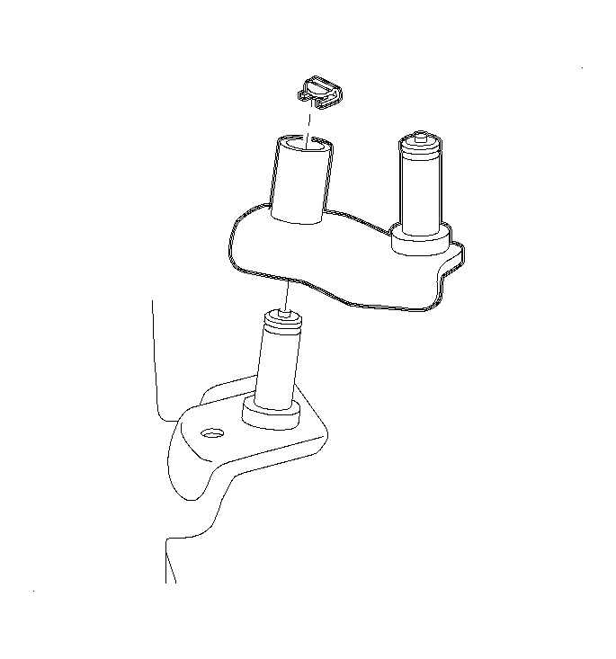
- If equipped with a manual transmission, disconnect the frame to shiftier link pivot pin clip.
 Courtesy of GENERAL MOTORS CORP.
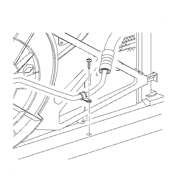
- Disconnect the A/C pipe to frame clip at the front of the vehicle.
 Courtesy of GENERAL MOTORS CORP.
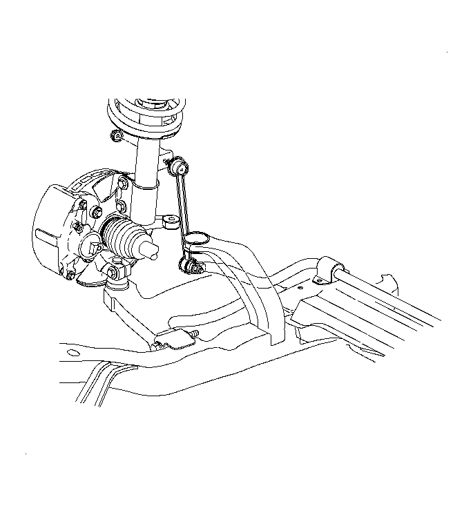
- Disconnect the stabilizer bar link from the struts. Discard the nuts.
 Courtesy of GENERAL MOTORS CORP.
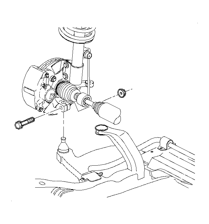
- Disconnect the lower control arms from the steering knuckle. Refer to Lower Control Arm Replacement
in Front Suspension.
 Courtesy of GENERAL MOTORS CORP.
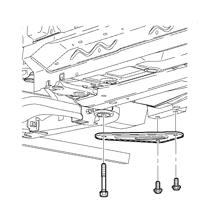
- Remove the suspension support assemblies. Discard the bolts.
- Remove the suspension support cage nuts from the body. Discard the nuts.
- Use a powertrain lifting table and the J 43628
to support the frame assembly. See Special Tools and Equipment .
 Courtesy of GENERAL MOTORS CORP.
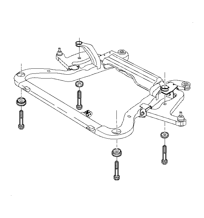
- Remove the remaining frame to body bolts. Discard the frame to body bolts.
- Lower the frame from the vehicle.
- Remove all frame assembly cage nuts from the body and discard.
 Courtesy of GENERAL MOTORS CORP.
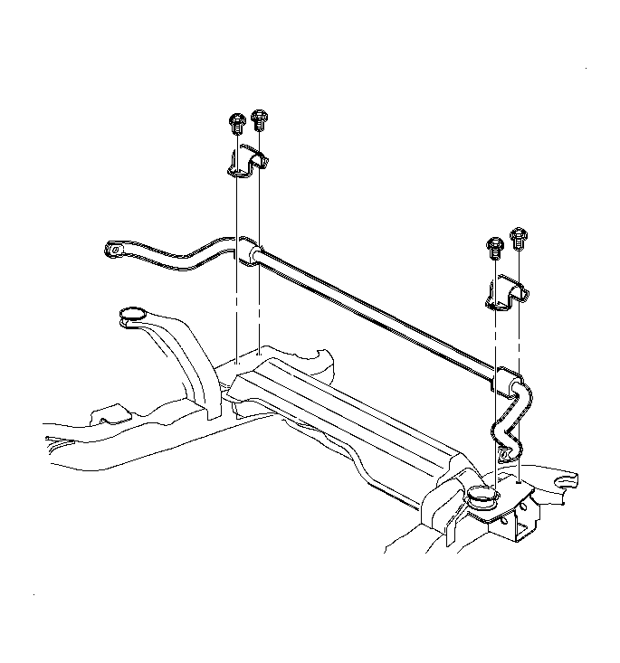
- Remove the stabilizer shaft assembly. Refer to Stabilizer Shaft Replacement (W/L61)
or Stabilizer Shaft Replacement (W/L81)
in Front Suspension.
 Courtesy of GENERAL MOTORS CORP.
- Remove the lower control arms. Refer to Lower Control Arm Replacement
in Front Suspension.
- Remove the frame assembly from the powertrain lifting table and the J 43628
. See Special Tools and Equipment .