Test 8: Motor Or Motor Relay Problem
- Ensure ignition is off. Disconnect ABS control unit harness connector. Turn ignition on. Measure voltage between terminals No. 1 and 20 at control unit harness connector. See Figure
. If battery voltage is not present, inspect and repair circuit(s) as necessary. See WIRING DIAGRAMS
. If battery voltage is present, go to next step.
- Turn ignition off. Remove ABS harness connector cover. Connect ABS control unit harness connector. Turn ignition on. Using voltmeter, backprobe harness connector. Measure voltage between terminals No. 17 and 20. See Figure
. If battery voltage is not present, replace ABS control unit. If battery voltage is present, go to next step.
- Turn ignition off. Disconnect ABS harness connector and hydraulic unit harness connector. Check for continuity between ABS control unit connector and hydraulic unit connector. See Figure
and Figure
. See HARNESS CONTINUITY CHECK table. If continuity exists, go to next step. If continuity does not exist, inspect and repair circuit as necessary. See WIRING DIAGRAMS
.
HARNESS CONTINUITY CHECK
| ABS Control Unit Terminal No. |
Hydraulic Unit Terminal No. |
| 17 |
6 |
| 32 |
11 |
| 27 |
12 |
- Turn ignition off. Disconnect hydraulic unit 2-pin connector. Measure voltage between ground and terminal No. 2 (White/Red wire) at harness connector. If battery voltage is not present, inspect and repair circuit as necessary. See WIRING DIAGRAMS
. If battery voltage is present, go to next step.
- Remove hydraulic unit motor relay. Hydraulic unit motor relay (4-terminal) is located on hydraulic unit. Check resistance of relay. See Fig 1
. Resistance should be infinite between terminals No. 30 and 87. With battery voltage applied across terminals No. 85 and 86, resistance should be zero ohms between terminals No. 30 and 87. Replace relay as necessary. If relay is okay, replace hydraulic unit.
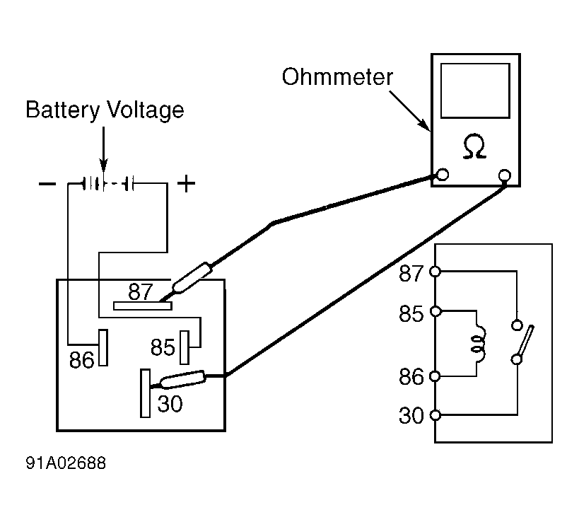 Courtesy of SUBARU OF AMERICA, INC.