DTC P1121: Neutral Position Switch Circuit Low Input (A/T)
- If DTC P0705 is present, diagnose DTC P0705 first. If DTC P1121 is only DTC set, turn ignition on. Using voltmeter connected to ground, backprobe ECM connector B135 (28-pin connector) terminal No. 26. See Figure. If voltage is 4.5-5.5 volts in gear positions other than Neutral or Park, circuit is normal. Check all connections. If voltage is not as specified, go to next step.
- Turn ignition off. Disconnect 12-pin in-line connector in transaxle harness between transaxle and ECM connector B135 (28-pin connector). Measure resistance between ground and ECM connector B135 (28-pin connector) terminal No. 26. If resistance is less than 10 ohms, repair short to ground in wiring between ECM and transaxle wiring connectors. See appropriate wiring diagram in WIRING DIAGRAMS
article. If resistance is 10 ohms or more, go to next step.
- Disconnect inhibitor switch connector. Measure resistance between transaxle-side of harness connector terminal No. 12 and ground. See Fig 1. If resistance is less than 10 ohms, repair short to ground in wiring. If resistance is 10 ohms or more, go to next step.
- Measure resistance of inhibitor switch between terminals No. 7 and 12 in all gear positions except Park and Neutral. See Figure. If resistance is one megohm or less, replace inhibitor switch. If resistance is more than one megohm, check selector cable and connection to inhibitor switch. Repair or replace as needed.
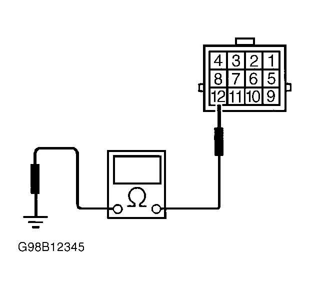 Courtesy of SUBARU OF AMERICA, INC.