Electrical Specification
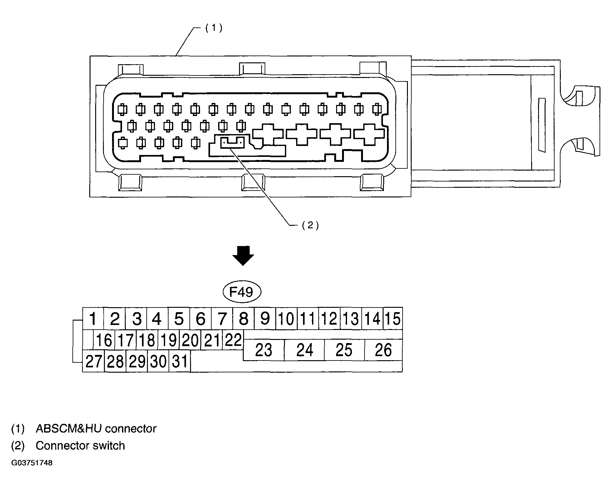 Courtesy of SUBARU OF AMERICA, INC.
NOTE:
- The terminal numbers in the ABS control module and hydraulic control unit connector are as shown in Fig 1
.
- When the connector is removed from the ABSCM&H/U, the connector switch closes the circuit between terminal No. 22 and No. 23. The ABS warning light illuminates.
INPUT/OUTPUT SIGNAL SPECIFICATION
| Contents |
Terminal No. (+)-(-) |
Input/Output signal |
| Measured value and measuring conditions |
| ABS sensor (Wheel speed sensor) |
Front left wheel |
9 - 10 |
0.12 - 1 V (When it is 20 Hz.) |
| Front right wheel |
11 - 12 |
| Rear left wheel |
7 - 8 |
| Rear right wheel |
14 - 15 |
| Valve relay power supply |
24 - 23 |
10 - 15 V |
| Motor relay power supply |
25 - 23 |
10 - 15 V |
| G sensor |
power supply |
30 - 28 |
4.75 - 5.25 V |
| ground |
28 |
- |
| output |
6 - 28 |
2.3+/-0.2 V when vehicle is in horizontal position. |
| Stop light switch |
2 - 23 |
Less than 1.5 V when the stop light is OFF and, 10 - 15 V when the stop light is ON. |
| ABS warning light |
22 - 23 |
Less than 1.5 V during 1.5 seconds when ignition switch is ON, and 10 - 15 V after 1.5 seconds. |
| AT ABS signal (AT model only) |
31 - 23 |
Less than 1.5 V when the ABS control still operates and more than 5.5 V when ABS does not operate. |
| ABS operation signal monitor |
3 - 23 |
Less than 1.5 V when the ABS control still operates and more than 5.5 V when ABS does not operate. |
| Select monitor |
Data is received. |
20 - 23 |
Less than 1.5 V when no data is received. |
| Data is sent. |
5 - 23 |
4.75 - 5.25 V when no data is sent. |
| Power supply |
1 - 23 |
10 - 15 V when ignition switch is ON. |
| Grounding line |
23 |
- |
| Grounding line |
26 |
- |