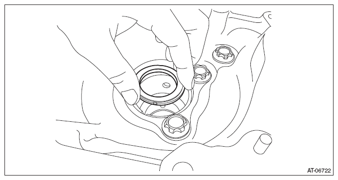
- Install the thrust bearing to the converter case.
NOTE:
Face the temper color surface to the converter case side.
 Courtesy of SUBARU OF AMERICA, INC.
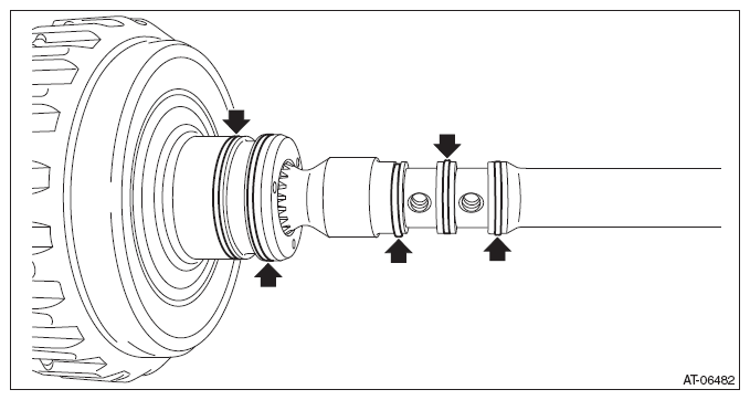
- Install the seal ring to the input shaft.
NOTE:
- Use new seal rings.
- When installing the seal rings, do not expand the seal rings too much.
- Apply CVTF to the seal rings.
 Courtesy of SUBARU OF AMERICA, INC.
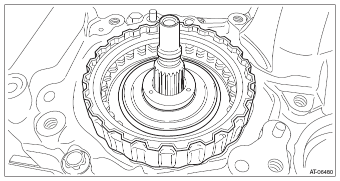
- Install the forward clutch assembly to the converter case.
 Courtesy of SUBARU OF AMERICA, INC.
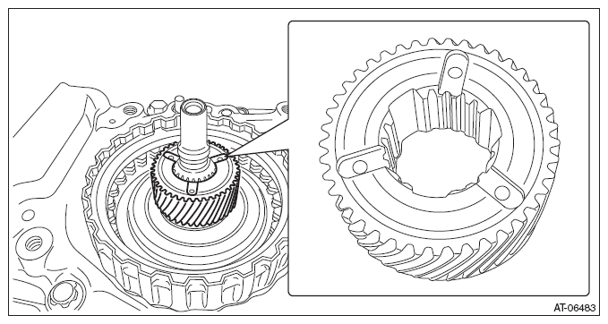
- Install the sun gear.
NOTE:
Face the end face of the sun gear to the reverse brake side as shown in the figure.
 Courtesy of SUBARU OF AMERICA, INC.
- Install the thrust bearing to the sun gear.
NOTE:
Face the temper color surface to the reverse brake side.
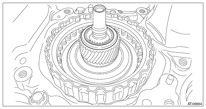 Courtesy of SUBARU OF AMERICA, INC.
- Install the planetary carrier.
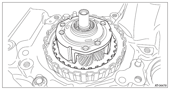 Courtesy of SUBARU OF AMERICA, INC.
- Install the thrust bearing.
NOTE:
Face the temper color surface to the reverse brake side.
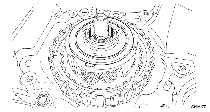 Courtesy of SUBARU OF AMERICA, INC.
- Install the internal gear.
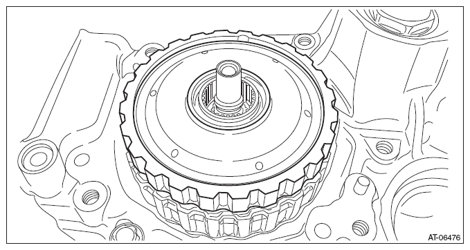 Courtesy of SUBARU OF AMERICA, INC.
- Install the thrust bearing to the internal gear.
NOTE:
Face the temper color surface to the reverse brake side.
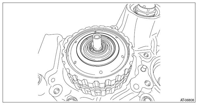 Courtesy of SUBARU OF AMERICA, INC.
- Select a washer. <Ref. to
ADJUSTMENT , Forward Clutch Assembly.>
- Install the reverse brake assembly. <Ref. to
INSTALLATION , Reverse Brake Assembly.>
- Install the primary pulley, secondary pulley and variator chain. <Ref. to
INSTALLATION , Primary Pulley and Secondary Pulley.>
- Install the reduction drive gear. <Ref. to
INSTALLATION , Reduction Drive Gear.>
- Install the transmission case. <Ref. to
INSTALLATION , Transmission Case.>
- Install the transmission control device. <Ref. to
INSTALLATION , Transmission Control Device.>
- Install the oil strainer and oil pan. <Ref. to
INSTALLATION , Oil Pan and Strainer.>
- Install the reduction driven gear assembly. <Ref. to
INSTALLATION , Reduction Driven Gear.>
- Install the transfer driven gear assembly. <Ref. to
INSTALLATION , Transfer Driven Gear.>
- Install the transfer clutch assembly. <Ref. to
INSTALLATION , Transfer Clutch.>
- Install the parking pawl. <Ref. to
INSTALLATION , Parking Pawl.>
- Install the extension case. <Ref. to
INSTALLATION , Extension Case.>
- Install the inhibitor switch. <Ref. to
INSTALLATION , Inhibitor Switch.>
- Install the secondary speed sensor. <Ref. to
INSTALLATION , Secondary Speed Sensor.>
- Install the primary speed sensor. <Ref. to
INSTALLATION , Primary Speed Sensor.>
- Install the turbine speed sensor. <Ref. to
INSTALLATION , Turbine Speed Sensor.>
- Install the transmission harness. <Ref. to
INSTALLATION , Transmission Harness.>
- Install the control valve body. <Ref. to
INSTALLATION , Control Valve Body.>
- Install the air breather hose. <Ref. to
INSTALLATION , Air Breather Hose.>
- Install the transmission assembly. <Ref. to
INSTALLATION , Automatic Transmission Assembly.>