Select lever: Assembly
- Installation of swivel
- Install the 2 washers, spacer, bushing, and swivel with a snap pin.
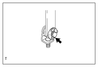 Courtesy of SUBARU OF AMERICA, INC.
- Installation of gasket
- Install 4 spacer plates and the gasket.
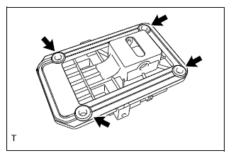 Courtesy of SUBARU OF AMERICA, INC.
- Installation of select arm bracket
- Apply Multemp D to the spring and the rod.
- Install the spring and the rod to the select arm bracket.
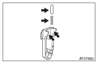 Courtesy of SUBARU OF AMERICA, INC.
- Apply Multemp D to the select lever COMPL and the select arm bracket.
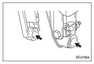 Courtesy of SUBARU OF AMERICA, INC.
- Apply Multemp D to the sliding surface of the rod and install the select arm bracket to the select lever COMPL.
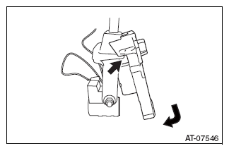 Courtesy of SUBARU OF AMERICA, INC.
- Installation of select lever COMPL
- Set the select arm bracket together with the select lever COMPL as a single unit to the base plate.
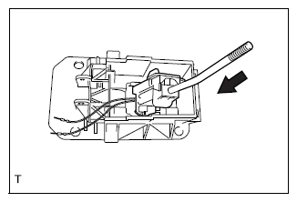 Courtesy of SUBARU OF AMERICA, INC.
- Installation of arm COMPL
- Insert the arm COMPL to the base plate.
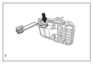 Courtesy of SUBARU OF AMERICA, INC.
- Use a pin punch 3 and hammer to drive in a new pin.
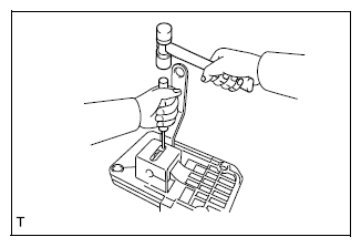 Courtesy of SUBARU OF AMERICA, INC.
- Installation of grommet
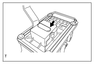
- Install the grommet.
 Courtesy of SUBARU OF AMERICA, INC.
- Installation of D rod
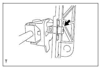
- Install the bushing D lock.
- Install the cushion detent lock to the D rod.
- Apply Multemp D to the D lock spring and the D rod.
- Install the D lock spring and the D rod.
- Install the D lock clamp.
 Courtesy of SUBARU OF AMERICA, INC.
- Installation of solenoid unit
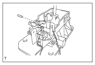
- Apply Multemp D to the solenoid unit and the pin.
- Set the solenoid unit together with the shift lock release arm as a unit to the base plate and insert the pin.
 Courtesy of SUBARU OF AMERICA, INC.
- Installation of guide plate
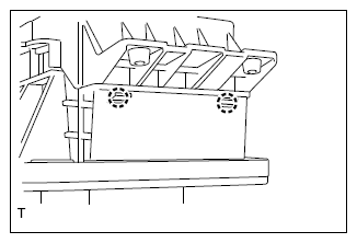
- Engage the 2 claws and install the guide plate to the base plate.
 Courtesy of SUBARU OF AMERICA, INC.
- Install the shaft guide pin and a new clamp push nut.
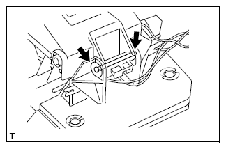 Courtesy of SUBARU OF AMERICA, INC.
- Connect the connectors No. 2 and No. 3 of the shift lock solenoid connector and the connectors No. 10 and No. 11 of the manual mode switch connector.
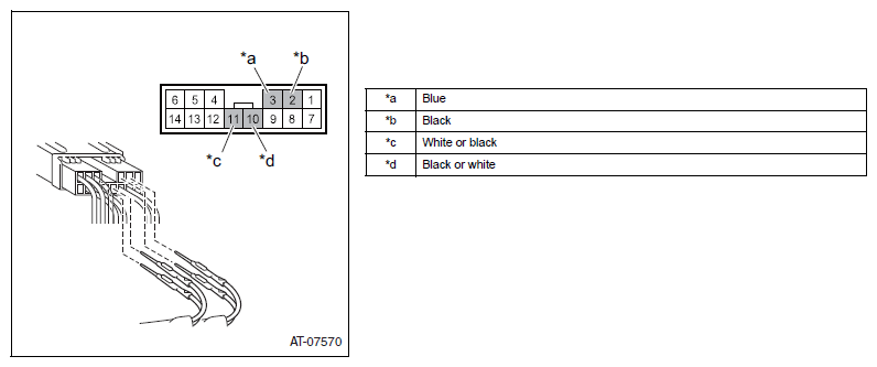 Courtesy of SUBARU OF AMERICA, INC.
- Lock the terminal of the harness connector.
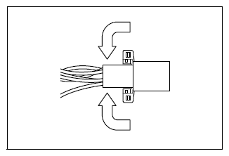 Courtesy of SUBARU OF AMERICA, INC.
- Engage the claw and install the connector.
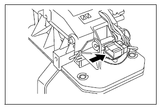 Courtesy of SUBARU OF AMERICA, INC.