- Pull on the inner halfshaft cup to confirm that the LH and RH rear drive unit halfshafts are fully seated on the rear drive unit, and that the circlip is locked into place.
NOTE:
If the halfshaft detaches from the rear drive unit, then reinstall the halfshaft paying attention to the following:
- Take care not to damage or displace the oil seals.
- Make sure that the opening of the snap rings are facing towards the bottom of the drive unit.
- Carefully push the halfshaft into the drive unit until there is an audible "click" from the halfshaft stub contacting the pinion shaft.
- There will be a slight pulling sensation on the halfshaft as the halfshaft circlip locks into place.
- Pull on the inner halfshaft cup to confirm that the circlip is locked into place.
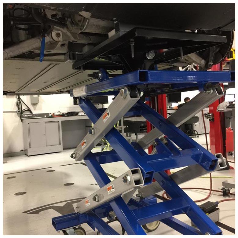
- Move the powertrain table with subframe to under the vehicle.
- Carefully raise the powertrain table.
CAUTION:
While raising the table, have an assistant monitor the underside of the vehicle. Make sure that there is sufficient clearance so that no components are damaged.
- Carefully raise the powertrain table so that the rear subframe is up against the body.
CAUTION:
While raising the table, occasionally stop to make sure no hoses, harnesses, or other components are caught or crushed. Also pay extra attention to the HV battery aero shield mounting tabs.
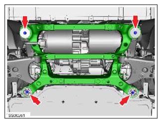
- Install and hand-tighten the bolts (x4) that secure the rear subframe to the body (torque 140 N.m).
 Courtesy of TESLA, INC. Courtesy of TESLA, INC.
|
- Use a crowbar to shimmy the rear subframe with respect to the body, so that the subframe mounting bolts are centered in the tracings, and the witness marks where the subframe contacts the body align.
NOTE:
It might be necessary to align one corner and tighten the bolt, align the opposite corner and tighten the bolt, and so on in a criss-cross pattern.
- Torque the bolts (x4) that secure the rear subframe to the body (torque 140 N.m).
- Lower the powertrain table and move it out from under the vehicle.
 Courtesy of TESLA, INC. Courtesy of TESLA, INC.
|
- If the drive unit was removed, refill the gearbox fluid. See Gearbox Fluid - Rear Small Drive Unit (Drain and Refill)
.
- Install the coolant hoses to the LH and RH sides of the drive unit.
- Move the coolant drain cart to the RH side of the drive unit.
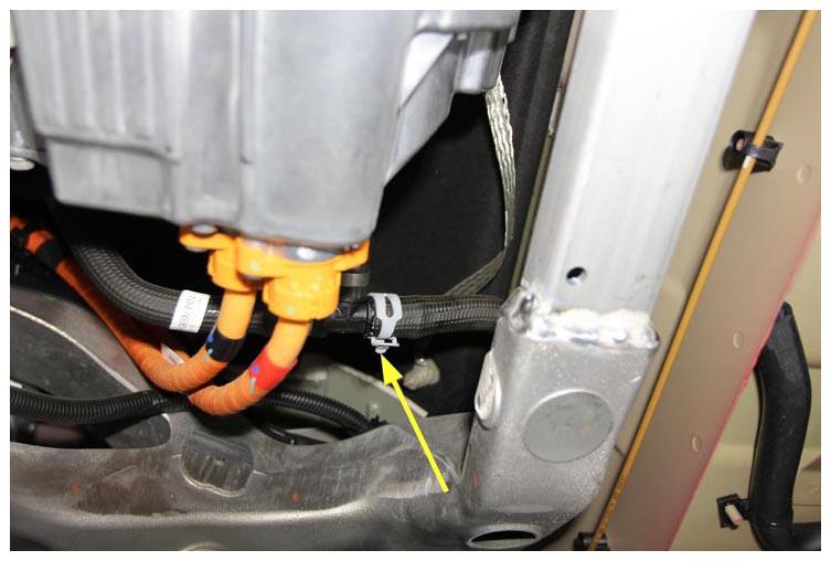
- Install the hose at the T-fitting, and then fasten the hose clamp.
 Courtesy of TESLA, INC. Courtesy of TESLA, INC.
|
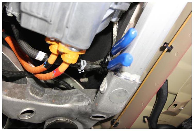
- Remove the hose clamping tool.
 Courtesy of TESLA, INC. Courtesy of TESLA, INC.
|
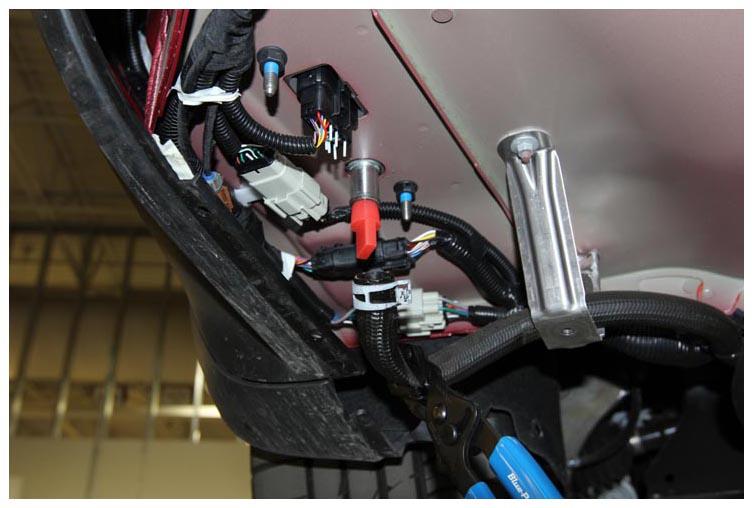
- Move the coolant drain cart to the LH side of the drive unit and charger fitting.
- Remove the plugs from the charger fitting, install the hose to the fitting, and then fasten the hose clamp.
 Courtesy of TESLA, INC. Courtesy of TESLA, INC.
|
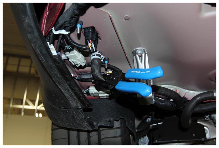
- Remove the hose clamping tool.
 Courtesy of TESLA, INC. Courtesy of TESLA, INC.
|
- Remove the drain cart from under the vehicle.
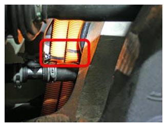
- Fasten the clips that secure the HV cables:
NOTE:
2 clips to the body
 Courtesy of TESLA, INC. Courtesy of TESLA, INC.
|
- Perform the following substeps on the drive unit:
- On the top RH side of the rear drive unit, install the ground strap to the drive unit (torque 6.5 N.m).
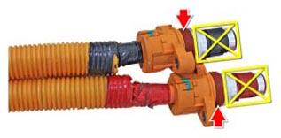
- Inspect the connector seals on the HV cables. If any are damaged, replace them.
- Apply P-80 emulsion to the connector seals.
CAUTION:
Do not apply P-80 emulsion to the HV terminals.
 Courtesy of TESLA, INC. Courtesy of TESLA, INC.
|
- Install the HV cables into the rear drive unit, and then install 4 new screws to secure the cables in the drive unit (torque 7 N.m).
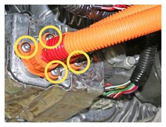 Courtesy of TESLA, INC. Courtesy of TESLA, INC.
|
- On the RH side of the drive unit, connect the logic connector.
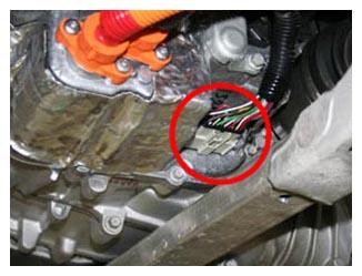 Courtesy of TESLA, INC. Courtesy of TESLA, INC.
|
- Install new O-rings (1003784-00-A or later) on the drive inverter cover and apply Silicone Lubricant (1010251-00-A) on both before installing the cover. Insert the cover at an angle to prevent damage to the O-rings. Once the left (B+) O-ring is seated, rotate the cover into position.
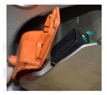 Courtesy of TESLA, INC. Courtesy of TESLA, INC.
|
- Connect the subframe harnesses to the body harness.
- Vehicles built through September 2014:
4 connectors at the back of the rear subframe
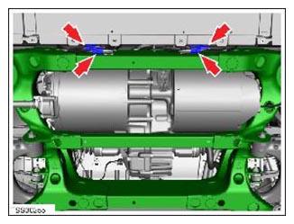 Courtesy of TESLA, INC. Courtesy of TESLA, INC.
|
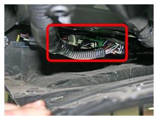
- Vehicles built after September 2014:
3 connectors above the RH side of the rear undershield
 Courtesy of TESLA, INC. Courtesy of TESLA, INC.
|
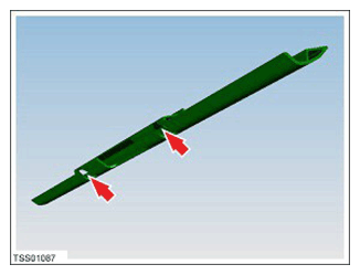
- If equipped, install the rear skid plate to the rear subframe, and then install the screws (x2) that secure the skid plate to the subframe (torque 10 N.m).
 Courtesy of TESLA, INC. Courtesy of TESLA, INC.
|
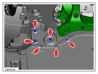
- Install the subframe shear plates to the subframe, fasten the clips (x2), and then install the nut (torque 35 N.m) and screws (x3) (torque 6 N.m) that secure each shear plate to the subframe.
 Courtesy of TESLA, INC. Courtesy of TESLA, INC.
|
- Install the mid aero shield. Refer to Panel - Aero Shield - Mid (Remove And Replace)
.
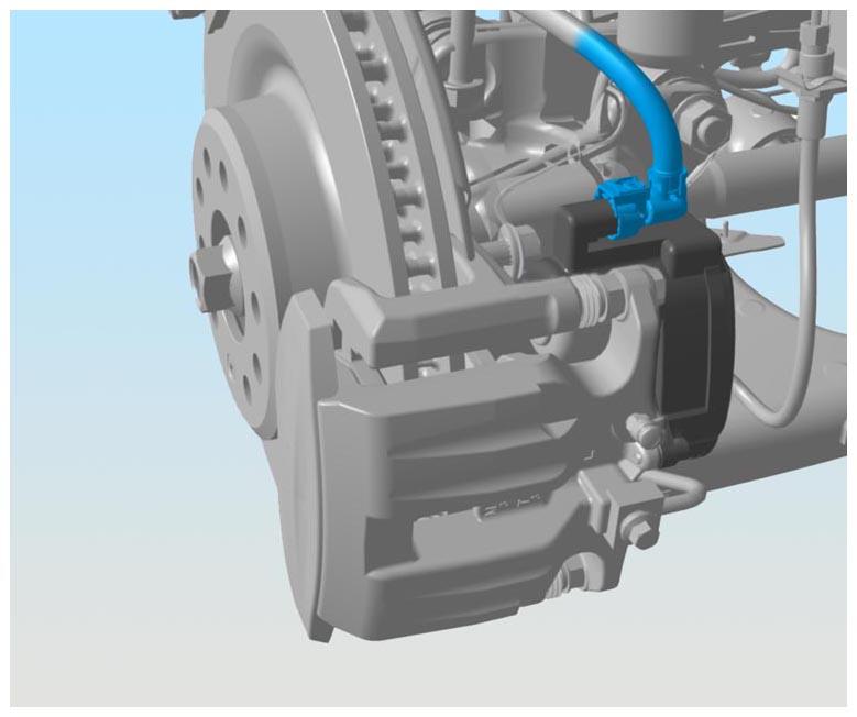
- Connect the electrical harnesses to the LH and RH parking brake connectors and then fasten the red locking tabs to secure the connectors.
NOTE:
Mando caliper shown; Brembo parking brake is a separate caliper
 Courtesy of TESLA, INC. Courtesy of TESLA, INC.
|
- Install the plastic park brake connector covers.
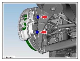
- On both sides of the vehicle, install the rear brake calipers to the rear knuckles, and then install the bolts (x2) that secure each caliper to each knuckle (torque 120 N.m).
CAUTION:
To avoid damage to the brake line, the brake caliper must be supported at all times.
 Courtesy of TESLA, INC. Courtesy of TESLA, INC.
|
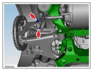
- On both sides of the vehicle, install and hand-tighten the nut that secures the rear shock absorber to the rear knuckle.
 Courtesy of TESLA, INC. Courtesy of TESLA, INC.
|
- Remove the bolt that attaches the LH rear brake rotor to the hub.
- Install the hub jack adapter onto the LH rear hub and hand-tighten the lug nuts.
- Use an underhoist stand to support the hub jack adapter.
- Measure the distance between the bottom of the quarter panel and the center of the rear axle to make sure that the rear suspension is set to ride height.
- Tighten the bolt and nut that attach the LH rear shock absorber to the LH rear knuckle (torque 140 N.m), and then mark the bolt and nut with a paint pen.
- Remove the underhoist stand from underneath the LH rear suspension.
- Remove the lug nuts that attach the hub jack adapter, and then remove the hub jack adapter from the hub.
- Install the bolt that attaches the LH rear brake rotor to the hub.
- Repeat step x through y for the RH side of the vehicle.
- Install the rear wheels. See Wheel (Remove and Install)
.
- Connect 12V power. See Disconnect 12V Power
.
- Perform a coolant air purge and top off the coolant.
- Open the coolant reservoir cap and fill the reservoir up to the NOM line.
- Carefully raise the powertrain table so that the rear subframe is up against the body.
- In Toolbox 3, click the Actions
tab, type "Coolant air purge" into the search field, click PROC_THC_X_COOLANT-AIR-PURGE, click Run
, and allow the routine to complete.
NOTE:
While the routine is running, monitor the coolant reservoir and add coolant as needed.
- Disconnect Toolbox and remove the laptop from the vehicle.
- Install the cap on the coolant reservoir.
- Remove the vehicle from the 2-post lift.
- Refer to the Alignment Requirement tables to determine whether an EPAS alignment check (EC) or four wheel alignment check (AC) is necessary. If performed, add the alignment check/adjust as a separate activity. See Alignment Requirement - Suspension
.