- Prepare the vehicle for lifting:
- Air suspension vehicles only:
Put the vehicle into Jack mode.
- Put the vehicle into Tow mode.
- Support the vehicle, but do not lift it at this time.
- Disconnect 12V power. Refer to Disconnect 12V Power
.
- Perform an electrical isolation check. See Vehicle Electrical Isolation Procedure
.
- Remove the rear wheels. See Wheel (Remove and Install)
.
- Raise the vehicle to working height.
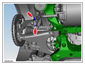
- On both sides of the vehicle, remove the nut that secures the shock absorber to the knuckle (torque 140 N.m), but do not remove the bolt yet.
 Courtesy of TESLA, INC. Courtesy of TESLA, INC.
|
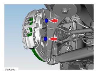
- On both sides of the vehicle, loosen the bolts (x2) that secure the brake caliper to the knuckle (torque 120 N.m). Remove and support the calipers.
CAUTION:
To avoid damage to the brake line, the brake caliper must be supported at all times.
 Courtesy of TESLA, INC. Courtesy of TESLA, INC.
|
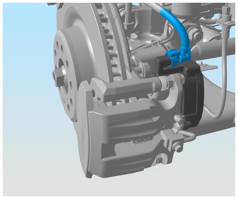
- Release the red locking tabs, and then disconnect the electrical harnesses from the LH and RH parking brake connectors.
NOTE:
Mando caliper shown; Brembo parking brake is a separate caliper
 Courtesy of TESLA, INC. Courtesy of TESLA, INC.
|
- Remove the mid aero shield. Refer to Panel - Aero Shield - Mid (Remove And Replace)
.
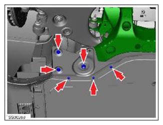
- Remove the subframe shear plates by removing the nut (torque 35 N.m), clips (x2), and screws (x3) (torque 6 N.m) that secure each shear plate to the subframe.
 Courtesy of TESLA, INC. Courtesy of TESLA, INC.
|
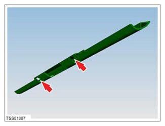
- If equipped, remove the screws (x2) that secure the rear skid plate to the subframe (torque 10 N.m).
 Courtesy of TESLA, INC. Courtesy of TESLA, INC.
|
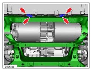
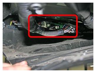
- Disconnect the subframe harnesses from the body harness.
- Vehicles built through September 2014:
4 connectors at the back of the rear subframe
 Courtesy of TESLA, INC. Courtesy of TESLA, INC.
|
- Vehicles built after September 2014:
3 connectors above the RH side of the rear undershield
 Courtesy of TESLA, INC. Courtesy of TESLA, INC.
|
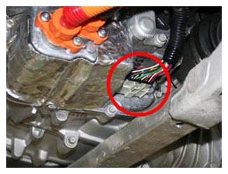
- On the RH side of the drive unit, disconnect the logic connector.
 Courtesy of TESLA, INC. Courtesy of TESLA, INC.
|
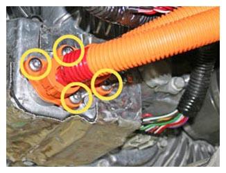
- Remove and discard the 4 screws that retain the HV cables (torque 7 N.m). Move the cables away from the drive unit.
 Courtesy of TESLA, INC. Courtesy of TESLA, INC.
|
- On the top RH side of the drive unit, release the ground strap from the drive unit (torque 6.5 N.m).
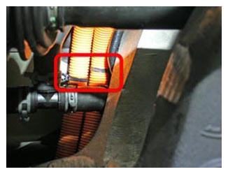
- Release the clips that secure the HV cables:
NOTE:
2 clips to the body
 Courtesy of TESLA, INC. Courtesy of TESLA, INC.
|
- Remove the coolant hoses from the LH and RH sides of the drive unit.
- Place a coolant drain cart near the LH side of the drive unit.
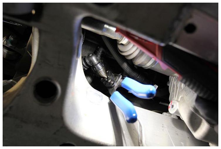
- Clamp the coolant output hose located between the subframe and chassis.
NOTE:
Pinch pliers steel
 Courtesy of TESLA, INC. Courtesy of TESLA, INC.
|
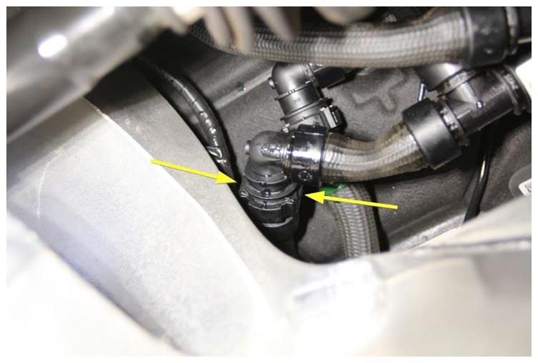
- Release the drive unit coolant outlet hose clip, and then disconnect the hose.
 Courtesy of TESLA, INC. Courtesy of TESLA, INC.
|
- Clamp the coolant inlet hose located between the subframe and chassis.
NOTE:
Pinch pliers steel
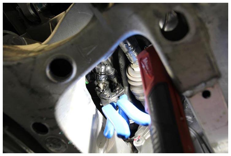 Courtesy of TESLA, INC. Courtesy of TESLA, INC.
|
- Release the drive unit coolant inlet hose clip, and then disconnect the hose.
NOTE:
Battery coolant drain kit - 1065131-00-A
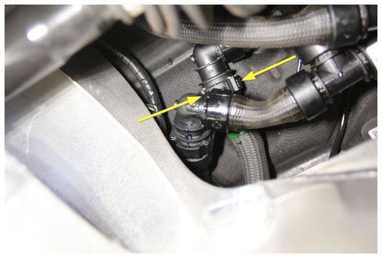 Courtesy of TESLA, INC. Courtesy of TESLA, INC.
|
- Move the coolant drain cart away from the working area.
- If the drive unit is being removed, drain the gearbox fluid. See Gearbox Fluid - Rear Small Drive Unit (Drain and Refill)
.
- Position the powertrain table with subframe fixture beneath the vehicle subframe.
- Connect shop air to the powertrain table.
- Carefully raise the powertrain table to support the rear subframe, aligning the subframe fixture dowels with the holes at the front of the subframe.
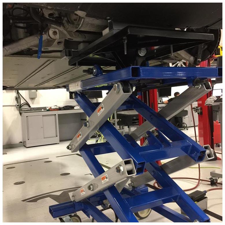 Courtesy of TESLA, INC. Courtesy of TESLA, INC.
|
- Use a paint pen to trace around each subframe mounting bolt, so that the bolts can be realigned later during the subframe installation.
- Use a paint pen to apply witness marks where the front/rear subframe contacts the body at each subframe mounting bolt, so that the subframe can be realigned to the body later during subframe installation.
NOTE:
Apply the witness marks at 90 degrees so that they indicate left/right and fore/aft movement.
- Remove the bolts (x4) that secure the rear subframe to the body (torque 140 N.m).
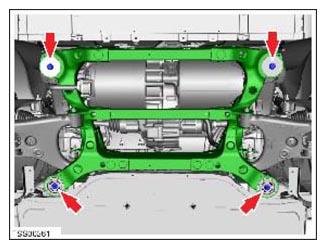 Courtesy of TESLA, INC. Courtesy of TESLA, INC.
|
- Carefully lower the powertrain table approximately 3 in (75 mm) to gain access to the remaining attachments.
CAUTION:
While lowering the table, occasionally stop to make sure no hoses, harnesses, or other components are caught or tangled. Also pay extra attention to the HV battery aero shield mounting tabs.
- Carefully lower the powertrain table.
CAUTION:
While raising the vehicle, have an assistant monitor the underside of the vehicle. Ensure that no components are still connected and that there is sufficient clearance so that no components are damaged.
- Move the powertrain table with subframe away from the vehicle.