- Position reverse idler gear in transmission case. Install Woodruff key in reverse idler gear shaft, then install shaft into case and through gear. Install reverse shift arm assembly.
NOTE:
Ensure punch mark on end of reverse shift arm pivot is positioned straight up before locking pivot nut.
- Lay countershaft in bottom of transmission case. Install output shaft assembly into transmission case. Drive output shaft rear bearing onto shaft and into case bore until it is fully seated.
- Install the 17 needle bearings into input shaft bore and use grease to hold them in place. Assemble synchronizer ring to synchronizer hub on input shaft. Using a plastic hammer, drive input shaft into transmission case.
NOTE:
Use care not to damage synchronizer ring when installing input shaft.
- Align countershaft with bores in case, then start rear bearing onto shaft and into case bore. Position front bearing on countershaft. Drive bearings onto shaft and into case bores by alternately tapping them with a plastic hammer.
- Install thrust washer and snap ring on rear of countershaft. Install large (outer) snap ring on countershaft front bearing. Select thickest snap ring that will properly fit groove on front end of countershaft, then install this snap ring on shaft.
NOTE:
Countershaft selective fit snap rings are available in the following thicknesses: .0807-.0827" (2.05-2.10 mm), .0846-.0866" (2.15-2.20 mm) and .0886-.0906" (2.25-2.30 mm).
- Install front bearing retainer and tighten attaching bolts. Install transmission side cover. Install rear bearing retainer and spacer.
- Place shift cover assembly and all gears in neutral position. Position shift cover assembly on transmission case, then install and tighten attaching bolts.
- Temporarily install transmission shift lever into shift cover assembly. While rotating input shaft check the shifting and output shaft rotational relationship.
- If abnormal noise develops while turning input shaft, correct by adjusting reverse shift arm pivot within range of 0 degrees to 45 degrees of marker point (punch mark). See Fig 1 .
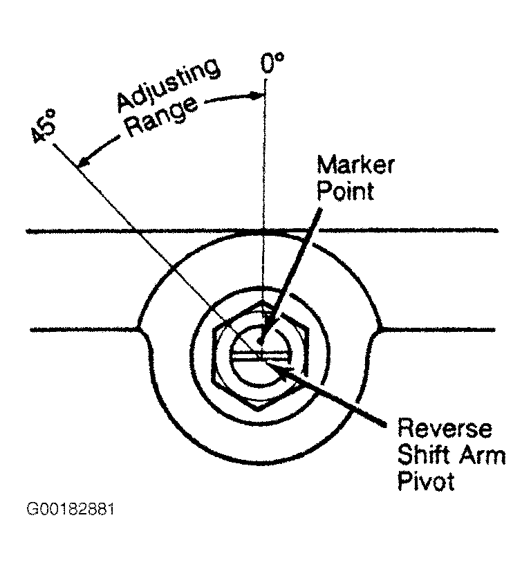 Courtesy of © TOYOTA, LICENSE AGREEMENT TMS1002