No Load Test
- Disconnect alternator terminal "B" wire. Using an ammeter and voltmeter, connect negative ammeter lead to disconnected alternator terminal "B" wire and positive lead to alternator terminal "B". Connect voltmeter positive lead to alternator terminal "B" and negative lead to ground. See Fig 1.
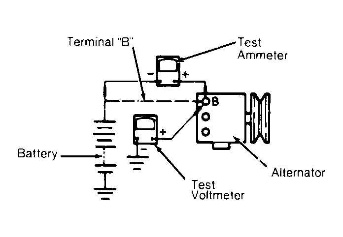 Courtesy of © TOYOTA, LICENSE AGREEMENT TMS1002
- Start engine and increase engine speed to 2000 RPM. Voltmeter and ammeter should read according to specification. See ALTERNATOR OUTPUT SPECIFICATIONS table.
- If voltage is more than specified, replace IC regulator. If voltage is less than specified, ground "F" (full field) terminal. See Fig 2.
- If voltage now climbs above specified range, replace IC regulator. If voltage remains below specified range, repair or replace alternator.
ALTERNATOR OUTPUT SPECIFICATIONS @ 2000 RPM
| Application |
Amps |
Volts |
| Cressida |
10 |
14.0-15.0 |
| Land Cruiser |
10 |
13.8-14.4 |
| All Others |
10 |
13.9-15.1 |
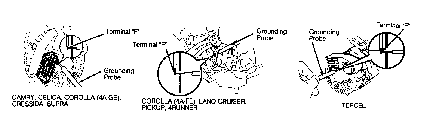 Courtesy of © TOYOTA, LICENSE AGREEMENT TMS1002