Diagnosis & Repair
- Ensure ignition is off. Disconnect ignitor 4-pin connector. Ignitor is in back of air cleaner housing. Turn ignition on. Using DVOM, measure voltage between terminal No. 2 of harness connector and ground. See Fig 1.
- If voltage is 9-14 volts, go to next step. If voltage is NOT 9-14 volts, inspect power supply circuit to ignitor. See wiring diagram in WIRING DIAGRAMS
article. Repair as needed.
- Turn ignition off. Disconnect 12-pin connector from ignitor. Turn ignition on. Measure voltage between harness connector terminals No. 4-6 and 10-12, and ground. See Fig 1. Voltage for all individual circuits should be 9-14 volts.
- If voltage for all circuits are within specification, go to step 6. If voltage for any circuit is NOT 9-14 volts, turn ignition off. Disconnect harness connector of suspect ignition coil connected to faulty ignitor circuit. See wiring diagram in WIRING DIAGRAMS
article.
- Measure resistance between suspect coil terminals. Resistance should be .54-.84 ohms for cold coil and .68-.98 ohms for hot coil. If resistances measured are NOT within specifications, replace coil. If resistances are within specification, inspect circuit(s) between coil and ignitor for shorts or opens. Repair as needed.
- Turn ignition off. Using ohmmeter, check continuity between ignitor 4-pin harness connector terminal No. 4 and ground. See Fig 1. If continuity exists, go to next step. If continuity does NOT exist, repair circuit and retest.
- Turn ignition on. Measure voltage between terminal No. 3 and ground. If voltage is 4.5-5.5 volts, go to next step. If voltage is NOT 4.5-5.5 volts, inspect IGF circuit between ECM and ignitor for open or short. See wiring diagram in WIRING DIAGRAMS
article. Repair as needed. If circuit is okay, replace ECM and retest.
- Inspect IGT1-IGT6 circuits between ignitor and ECM for opens or shorts. Repair as needed. If all circuits are okay, turn ignition on. Measure voltage between terminals No. 15, 16, 24, 26, 29 and 30 (IGT1-IGT6) of ECM connector, and ground while cranking engine.
- Voltage should be .5-1.0 volts for each circuit. If voltage for all circuits are within specification, replace ignitor and retest. If voltage for any circuit is NOT within specification, replace ECM and retest.
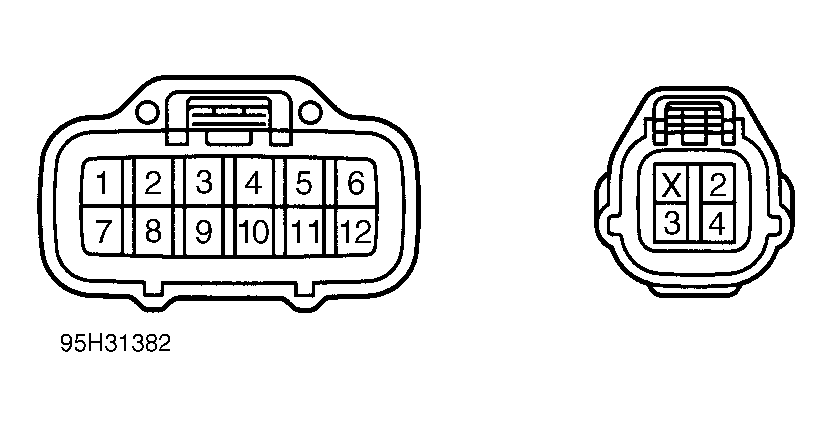 Courtesy of © TOYOTA, LICENSE AGREEMENT TMS1002