Diagnostic Procedure
- If ABS warning light remains illuminated, go to step 3). If ABS warning light does not illuminate, check light bulb and replace as necessary. If bulb is okay, diagnose combination meter (instrument panel). See INSTRUMENT PANEL article in ACCESSORIES/SAFETY EQUIPMENT section. If combination meter is okay, go to next step.
- Turn ignition off. Disconnect ABS control relay. Using DVOM, check for continuity between specified relay terminals. See ABS CONTROL RELAY INSPECTION table. Replace relay if continuity is not as specified. If relay is okay, check for open in wiring harness between DLC1, ABS control relay and chassis ground. See WIRING DIAGRAMS . Repair as necessary.
- Retrieve DTCs. See RETRIEVING DTCS under SELF-DIAGNOSTICS . If a DTC is present, perform appropriate test under DIAGNOSTIC TESTS . If no DTCs are present, go to next step.
- Remove short pin from DLC1. If ABS warning light turns off, go to next step. If ABS warning light does not turn off, check for short in wiring harness between ABS warning light, DLC1 and ABS ECU. See WIRING DIAGRAMS . Repair as necessary.
- Check ABS control relay following procedures in step 2). Replace as necessary. If relay is okay, check for short in wiring harness between DLC1 and ABS control relay. See WIRING DIAGRAMS . Repair as necessary.
ABS CONTROL RELAY INSPECTION
| Condition |
Terminals |
Specification |
| De-energized |
A7-1 & A6-3 |
80 Ohms |
| A7-5 & A7-6 |
Continuity |
| A7-2 & A7-5 |
Open |
| A7-4 & A7-5 |
Continuity |
| Energized |
A7-5 & A7-6 |
Open |
| A7-2 & A7-5 |
Continuity |
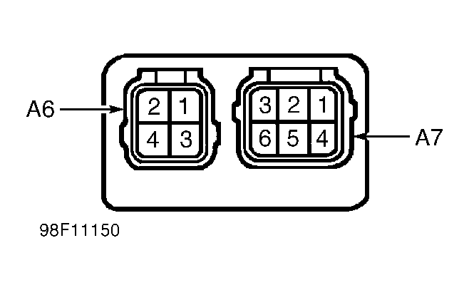 Courtesy of © TOYOTA, LICENSE AGREEMENT TMS1002