Ignition Switch
- Disconnect electrical connector from ignition switch on steering column. See Figure. Note ignition switch electrical terminal identification and ignition lock cylinder positions. See Fig 1.
- Using ohmmeter, check that continuity is as specified between indicated ignition switch electrical terminals in relation to ignition lock cylinder position. See IGNITION SWITCH CONTINUITY table. Replace ignition switch if defective.
IGNITION SWITCH CONTINUITY
| Lock Cylinder Position |
Ignition Switch Pins No. |
Specification |
| LOCK |
|
|
| ACC |
2 & 3 |
Continuity |
| ON |
2, 3 & 4; 6 & 7 |
Continuity |
| START |
1, 2 & 4; 6, 7 & 8 |
Continuity |
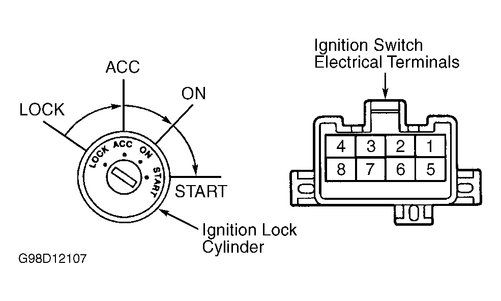 Courtesy of © TOYOTA, LICENSE AGREEMENT TMS1002