Power Door Lock Control Relay/Integration Relay Circuit Tests
NOTE:
For anti-theft and power door lock ECU circuit testing, see appropriate ANTI-THEFT SYSTEMS article.
Checking pin voltages at power door lock integration control relay or integration relay connectors will help determine if power door lock integration control relay and integration relay are receiving and sending proper signals. Tests may also help determine if there is a short or open in harness or connectors. Measure between ground and specified terminal. See appropriate POWER DOOR LOCK CONTROL & INTEGRATION RELAY TEST table.
Unless stated otherwise in testing procedures, perform all voltage tests using a Digital Volt-Ohmmeter (DVOM) with a minimum 10 k/ohm input impedance. Voltage readings may vary slightly due to battery condition or charging rate.
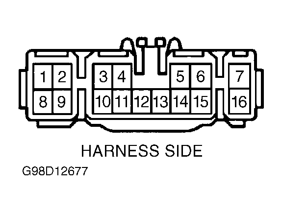
POWER DOOR LOCK CONTROL & INTEGRATION RELAY CIRCUIT TEST (1999 CELICA)
| Terminal No. |
Condition |
Continuity? |
| 2 |
Passenger Door Courtesy Switch OFF (Door Closed) |
No |
| 2 |
Passenger Door Courtesy Switch OFF (Door Open) |
Yes |
| 5 |
Passenger's Door Lock Set To LOCK |
No |
| 5 |
Passenger's Door Lock Set To UNLOCK |
Yes |
| 6 |
Driver Door Lock Set To LOCK |
No |
| 6 |
Driver Door Lock Set To UNLOCK |
Yes |
| 9 |
Driver Door Lock Set To LOCK |
No |
| 9 |
Driver Door Lock Set To UNLOCK |
Yes |
| 10 |
Door Lock Control Switch Position UNLOCK |
No |
| 10 |
Door Lock Control Switch Position LOCK |
Yes |
| 11 |
Door Lock Control Switch Position LOCK |
No |
| 11 |
Door Lock Control Switch Position UNLOCK |
Yes |
| 12 |
Door Key Lock & Unlock Switch Position UNLOCK |
No |
| 12 |
Door Key Lock & Unlock Switch Position LOCK |
Yes |
| 13 |
Door Key Lock & Unlock Switch Position LOCK |
No |
| 13 |
Door Key Lock & Unlock Switch Position UNLOCK |
Yes |
| 14 |
Driver Door Courtesy Switch OFF (Door Closed) |
No |
| 14 |
Driver Door Courtesy Switch ON (Door Opened) |
Yes |
| 15 |
Constant |
Yes |
| 16 |
Constant |
Yes |
| 7 |
Ignition Switch Position LOCK |
Yes |
| 8 |
Constant |
B+ |
| 1 |
Ignition Switch Position LOCK Or ACC |
No Voltage |
| 5 |
Ignition Switch Position ON |
B+ |
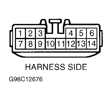
POWER DOOR LOCK CONTROL & INTEGRATION RELAY CIRCUIT TEST (COROLLA)
| Terminal No. |
Condition |
Continuity? |
| 1 |
Driver & Passenger Door Lock Control Switch UNLOCK |
No |
| 1 |
Driver & Passenger Door Lock Control Switch OFF |
No |
| 1 |
Driver & Passenger Door Lock Control Switch LOCK |
Yes |
| 2 |
Driver & Passenger Door Lock Control Switch LOCK |
No |
| 2 |
Driver & Passenger Door Lock Control Switch OFF |
No |
| 2 |
Driver Or Passenger Door Lock Control Switch UNLOCK |
Yes |
| 3 |
Driver & Passenger Door Key Lock & Unlock Switch UNLOCK |
No |
| 3 |
Driver & Passenger Door Key Lock & Unlock Switch OFF |
No |
| 3 |
Driver Or Passenger Door Key Lock & Unlock Switch LOCK |
Yes |
| 5 |
Driver Door Key Lock & Unlock Switch LOCK Or OFF |
No |
| 5 |
Driver Door Key Lock & Unlock Switch UNLOCK |
Yes |
| 6 |
Passenger Door Key Lock & Unlock Switch LOCK |
No |
| 6 |
Passenger Door Key Lock & Unlock Switch OFF |
No |
| 6 |
Passenger Door Key Lock & Unlock Switch UNLOCK |
Yes |
| 9 |
Passenger Door Courtesy Switch OFF (Door Closed) |
No |
| 9 |
Passenger Door Courtesy Switch ON (Door Opened) |
Yes |
| 10 |
Driver Door Unlock Detection Switch OFF (Door Locked) |
No |
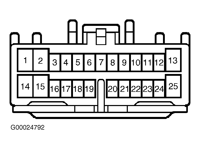
POWER DOOR LOCK CONTROL & INTEGRATION RELAY CIRCUIT TEST (ECHO)
| Terminal No. |
Condition |
Continuity? |
| 3 |
Ignition Switch OFF |
No Voltage |
| 3 |
Ignition Switch ON |
Battery Voltage |
| 5 |
Driver Door UNLOCK Detection Switch Off (Door Locked) |
No |
| 5 |
Driver Door UNLOCK Detection Switch ON (Door Unlocked) |
Yes |
| 7 |
Driver & Passenger Door Lock Control Switch UNLOCK Or Off |
No |
| 7 |
Driver Or Passenger's Door Lock Control Switch LOCK |
Yes |
| 8 |
Driver & Passenger Door Lock Control Switch LOCK Or Off |
No |
| 8 |
Driver Or Passenger Door Lock Control Switch UNLOCK |
Yes |
| 9 |
Driver Door Lock & UNLOCK Control Switch UNLOCK Or Off |
No |
| 9 |
Driver Door Key Lock & Unlock Switch LOCK |
Yes |
| 9 |
Front Passenger Door Key Lock & Unlock Switch UNLOCK Or OFF |
No |
| 9 |
Front Passenger Door Key Lock & Unlock Switch LOCK |
Yes |
| 10 |
Driver Door Key Lock & Unlock Switch LOCK Or OFF |
No |
| 10 |
Driver Door Key Lock & Unlock Switch UNLOCK |
Yes |
| 11 |
Front Passenger Door Key Lock & Unlock Switch LOCK Or Off |
No |
| 11 |
Front Passenger Door Key Lock & Unlock Switch UNLOCK |
Yes |
| 14 |
On At All Times |
Battery Voltage |
| 18 |
Driver's Door Courtesy Switch OFF |
No |
| 18 |
Driver's Door Courtesy Switch ON |
Yes |
| 19 |
Front Passenger Door Courtesy Switch OFF |
No |
| 19 |
Front Passenger Door Courtesy Switch On |
Yes |
| 19 |
Rear Left Side Door Courtesy Switch ON |
Yes |
| 19 |
Rear Left Side Door Courtesy Switch OFF |
No |
| 19 |
Rear Left Side Door Courtesy Switch ON |
Yes |
| 25 |
On At All Times |
Yes |
 Courtesy of © TOYOTA, LICENSE AGREEMENT TMS1002
 Courtesy of © TOYOTA, LICENSE AGREEMENT TMS1002
 Courtesy of © TOYOTA, LICENSE AGREEMENT TMS1002